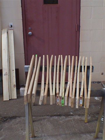
Fig. 1 Lumber from Home Depot
that's too warped to be sold.
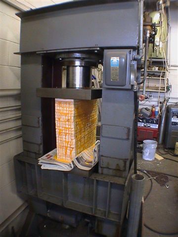
Fig. 2 Warped wood is no match
for a 15,000-lb. squeeze in Bill's desigmed-and-built (100-ton squeeze) hydraulic press.
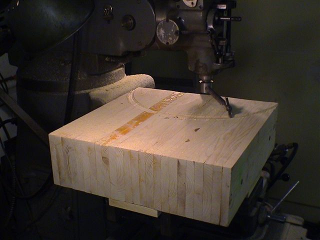
Fig. 3 Squaring up the glued block.
Note the direction of the alternating end grain for each layer.
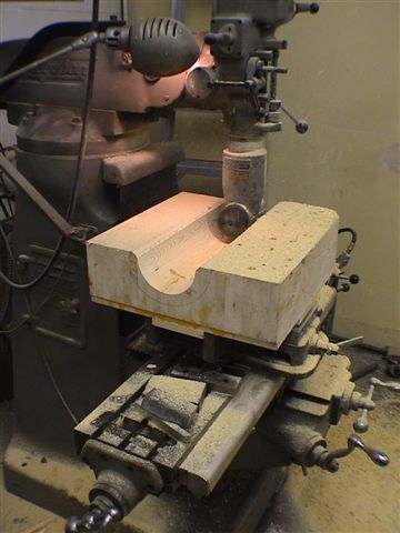
Fig. 4 Core box fabrication, main axis.
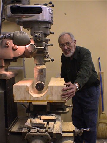
Fig. 5 Main axis cut nearly done.
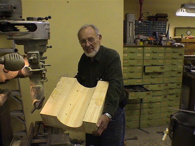
Fig. 6 Main axis roughing cut finished.
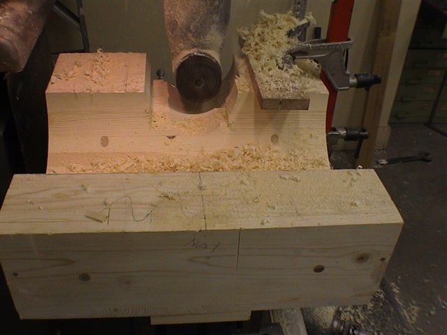
Fig. 7 Core box: cross axis cut.
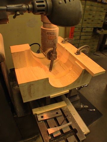
Fig. 8 Core box: fillet details.
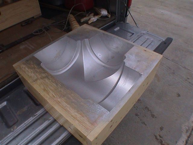
Fig. 9 The finished core box
with silver mold release applied.
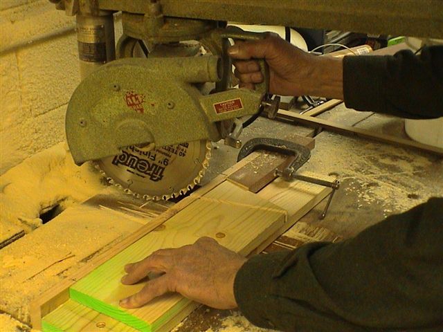
Fig. 1 Setup for cutting
"pie-shaped" wood blocks.
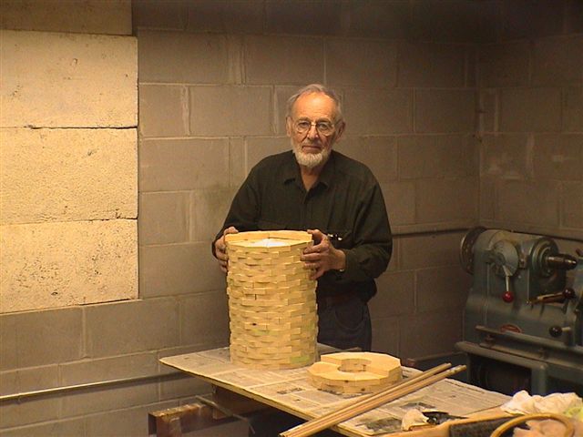
Fig. 2 Finally, I have cut 350 pieces.
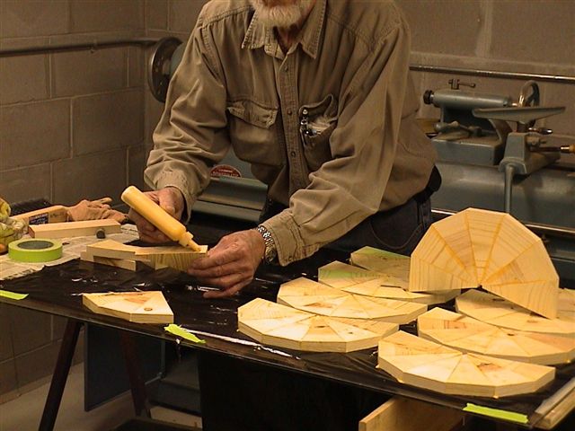
Fig. 3 Gluing "pie" section together.
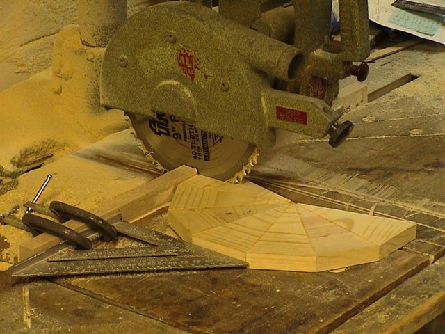
Fig. 4 Stagger cut for alternate layer overlap.
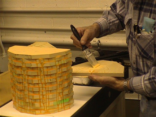
Fig. 5 Gluing layers together.
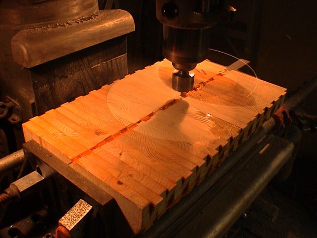
Fig. 6 "Fly" cutting the half pattern match face.
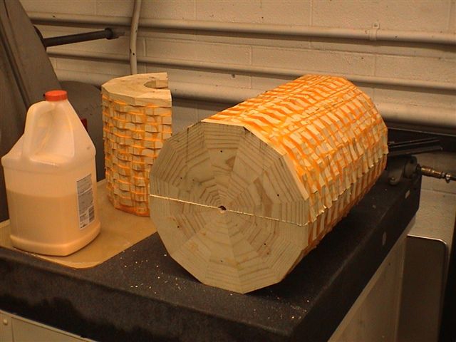
Fig. 7 Two halves make a cylinder.
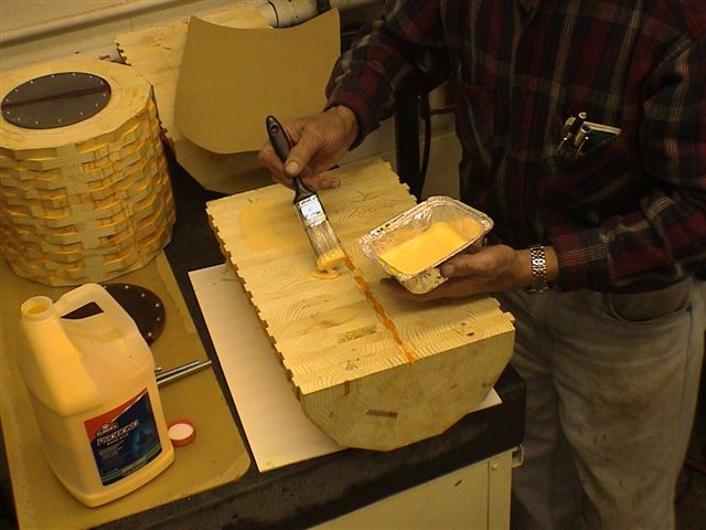
Fig. 8 Elmer's Professional Glue on flycut face.
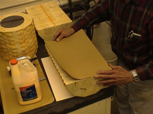
Fig. 9 Kraft paper in joint allows splitting later.
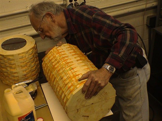
Fig. 10 Last chance to align pattern halves.
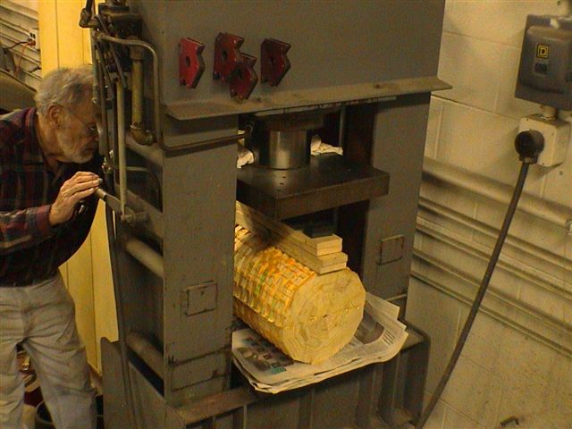
Fig. 11 Putting the squeeze on in the hydraulic press.
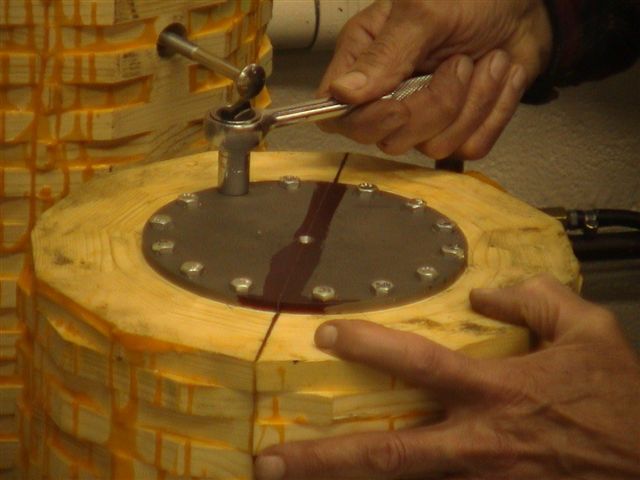
Fig. 12 Steel end plate provides rugged center hole.
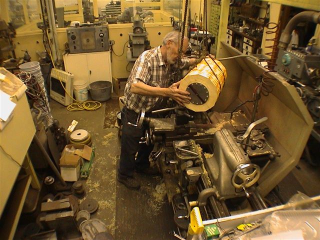
Fig. 13 Shop crane was handy for loading in lathe.
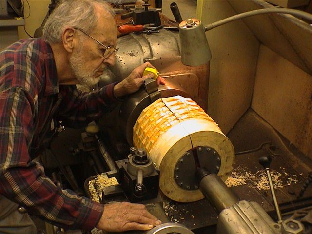
Fig. 14 Lathe barely big enough.
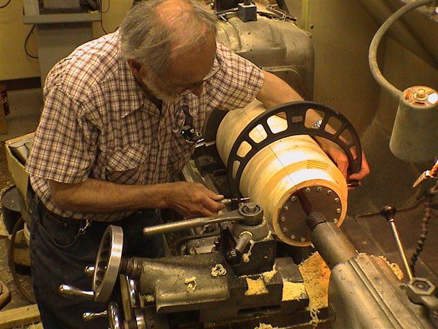
Fig. 15 .006-in. taper on first pass was corrected.
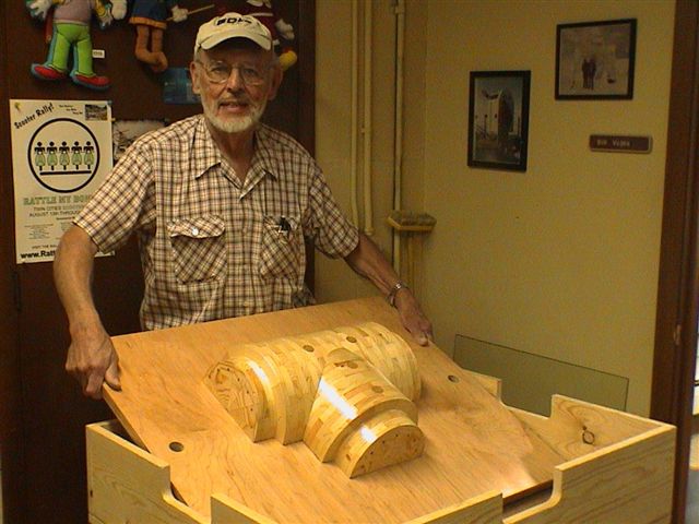
Fig. 16 Cylinder split on Kraft joint, mounted on 1 in. ply.
Robert Carity, Carley Foundry engineer,
took the pictures used in Fig. 3 through Fig. 14.
Fig. 1 Finished match plate pattern on 7 Sep 2009.
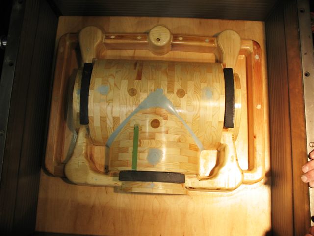
Fig. 2 Cast iron chills added at Carley Foundry.
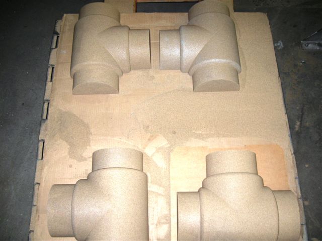
Fig. 3 Sand half cores made with core box
(see Make Core Box Figure 9)
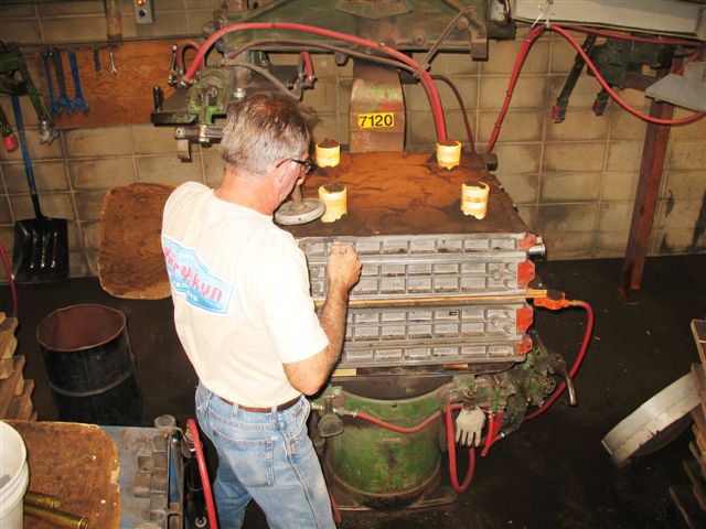
Fig. 4 Making the mold at Carley Foundry.
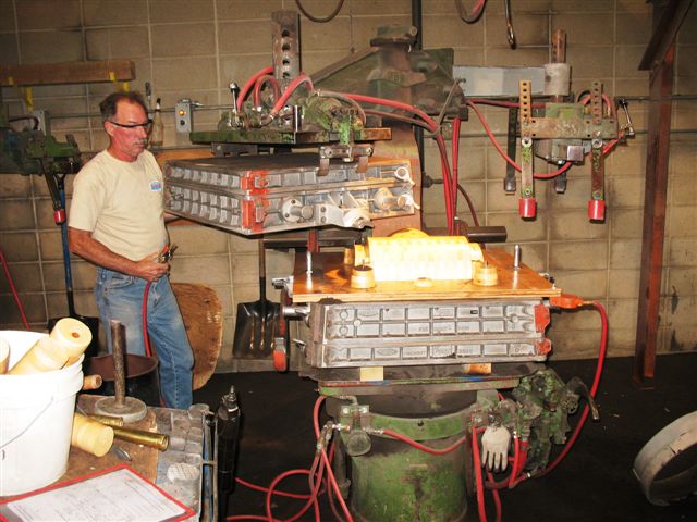
Fig. 5 Lifting the upper mold half off the pattern.
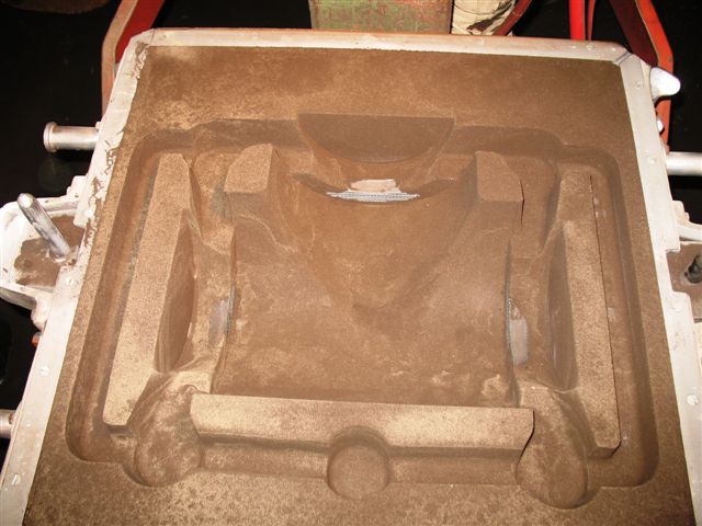
Fig. 6 Pattern impression in sand mold.
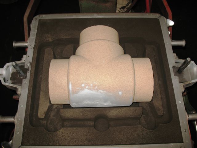
Fig. 7 Core in mold to produce a hollow casting.
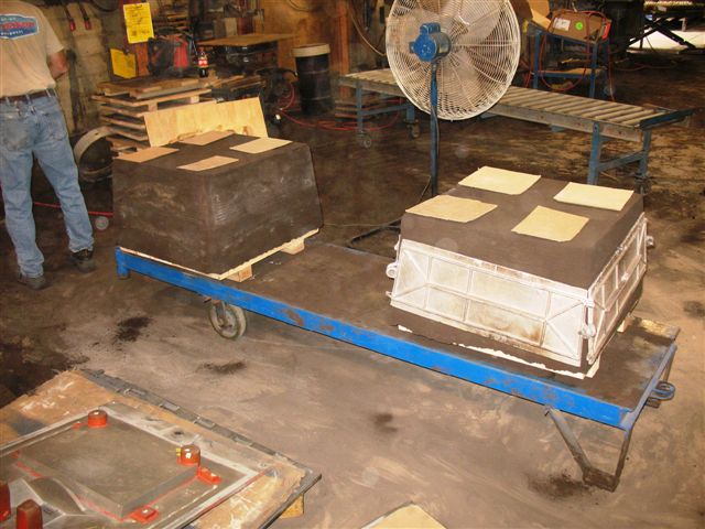
Fig. 8 Molds ready for the "pour."
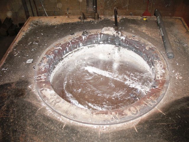
Fig. 9 2,500 lbs. of molten aluminum are ready.
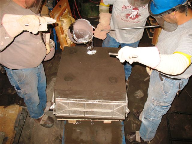
Fig. 10 The "pour" begins at Carley Foundry.
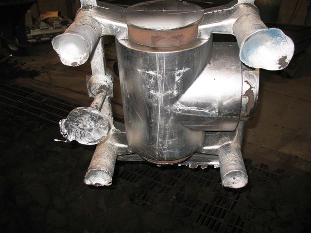
Fig. 11 Front view of two castings, showing gates and risers.
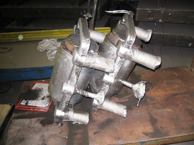
Fig. 12 Side view of the castings in Fig 11.
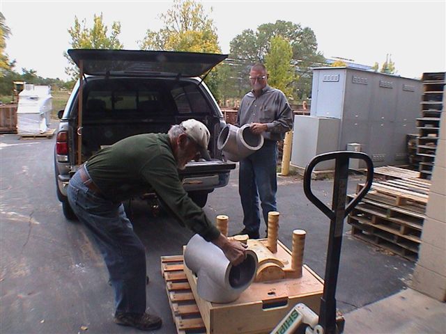
Fig. 13 Cast weight right on with CAD prediction.
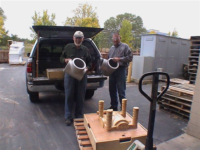
Fig. 14 These castings are impressive.
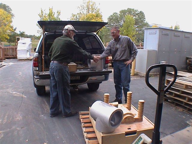
Fig. 15 Bob Carity, Carley engineer, handing finished castings to Bill.
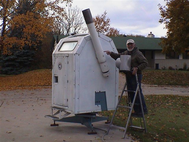
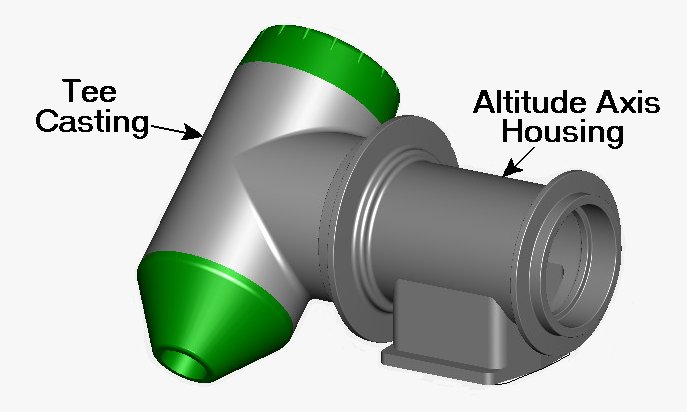
Fig. 16 On TARDIS I, Bill points to the future location
of the casting for TARDIS II.
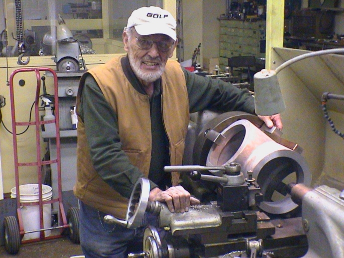
Fig. 1 First cut on tee casting.
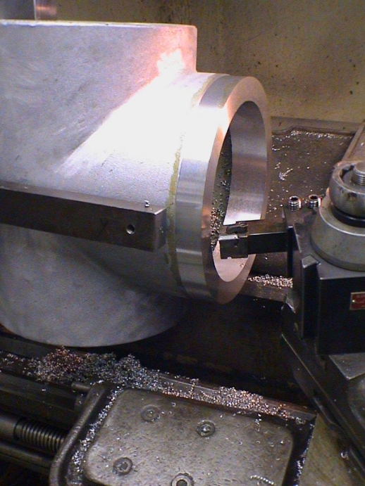
Fig. 2 Tool-machine setups for tee casting.

Fig. 3 Finished o-ring groove.
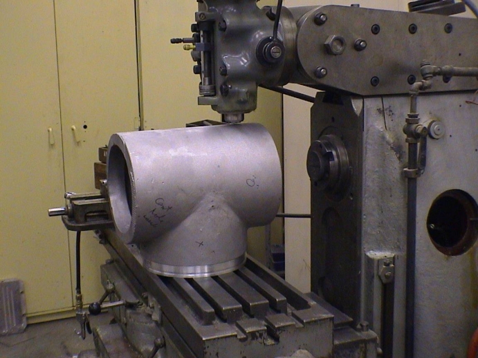
Fig. 4 Considering options for further machining.