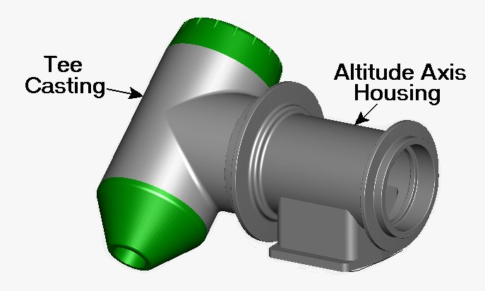
This is the housing for the altitude axis bearings and spindle asssembly. The aluminum casting was designed using
Shark FX software.
A significant difference between this core box and the earlier Tee Casting core box was its lack of main axis symmetry. This made it necessary to fabricate a complete, two-sided box, because two half-sided cores could not be cemented together for the casting, as was done for the Tee Casting.
The following pictures show this feature with its several fabrication challenges. Replacement 12 x 24 inch jaws for the mill vice proved very helpful to produce similitude in the two halves. Fabrication took eleven months of spare time.
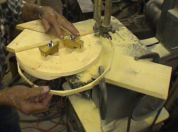
Fig. 1 Sawing half-circle pieces.
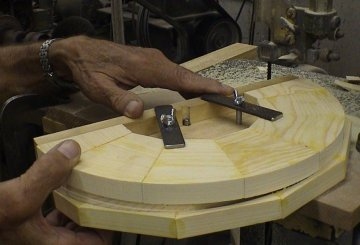
Fig. 2 Sawing half-circle piece completed.
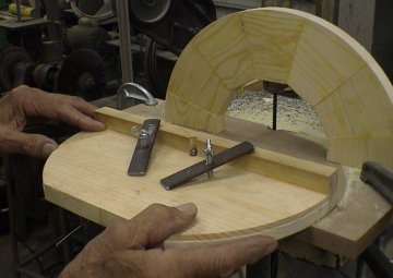
Fig. 3 Fixture for sawing half-circles.
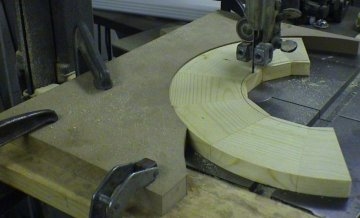
Fig. 4 Fixture for cutting inside radius.
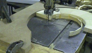
Fig. 5 Completed cut.
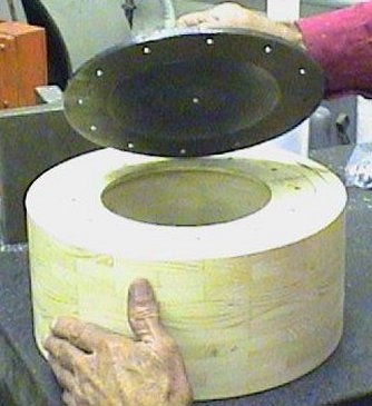
Fig. 6 Attaching driver plate to glued stack.
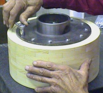
Fig. 7 Fixture plate lag bolts.
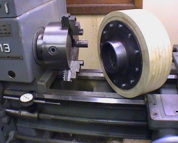
Fig. 8 Fixture plate and glue-up ready for lathe.
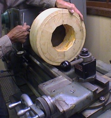
Fig. 9 Tightening the chuck.
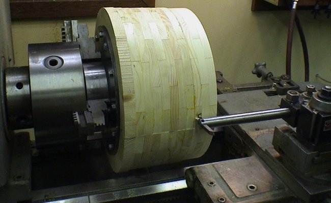
Fig. 10 Initial cutting on the stack.
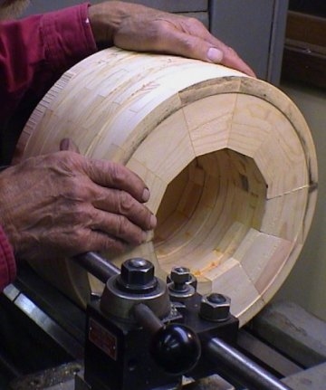
Fig. 11 First internal cut on the stack.
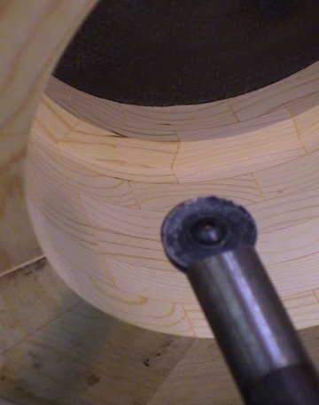
Fig. 12 Custom-made radius tool boring bar.
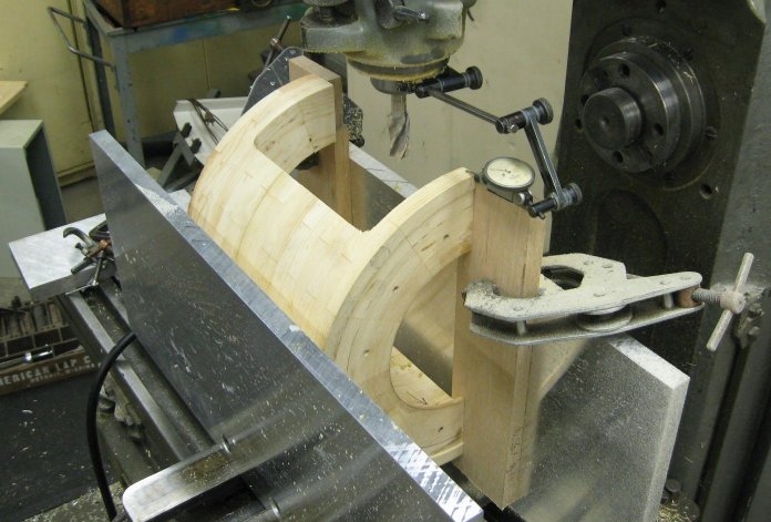
Fig. 13 Indicating for a perpendicular cut.
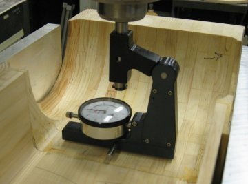
Fig. 14
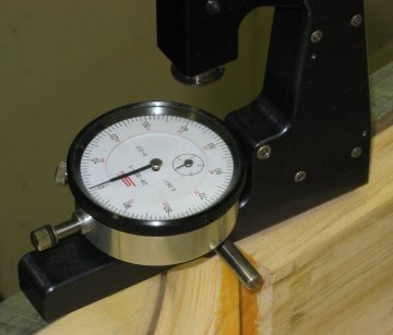
Fig. 15
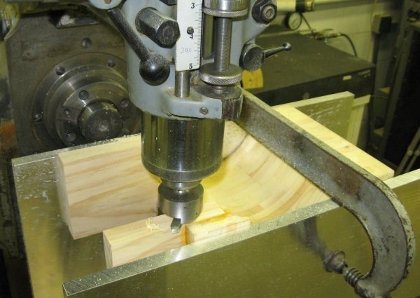
Fig. 16
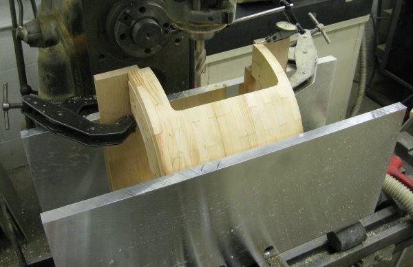
Fig. 17
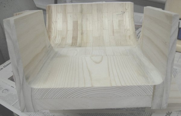
Fig. 18 Side arm grain pattern.
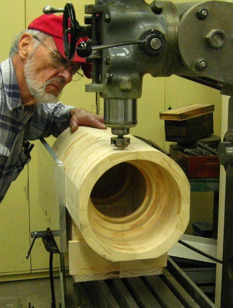
Fig. 19 Fly cut for match.
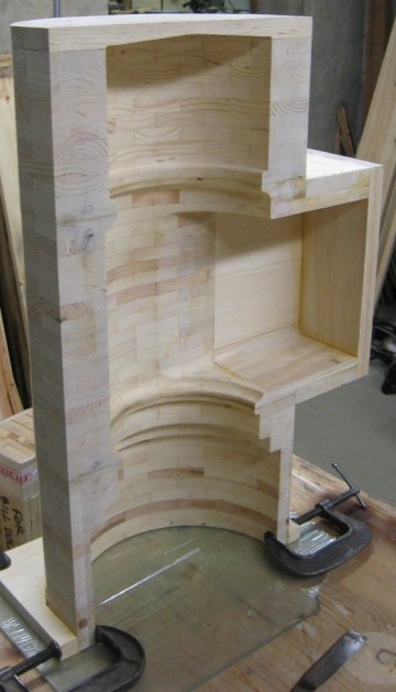
Fig. 20 Super structure start.
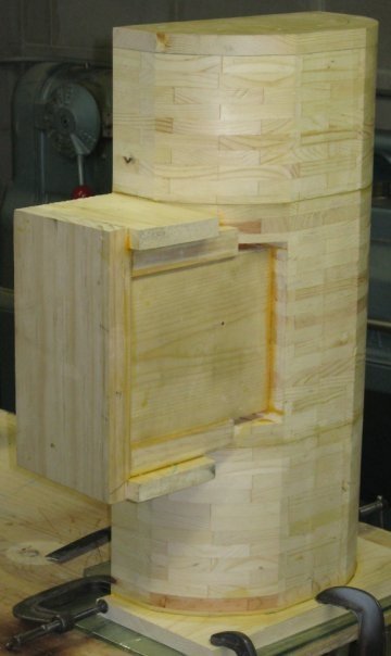
Fig. 21
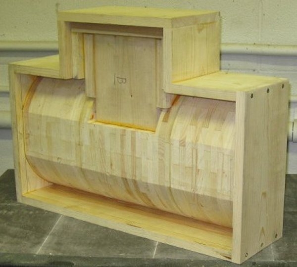
Fig. 22 Bottom view details.
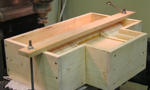
Fig. 23 Setup for fly cutting core box edges.
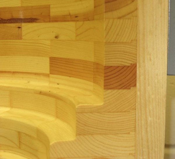
Fig. 24 Alternating grain structure and layer alignment key.
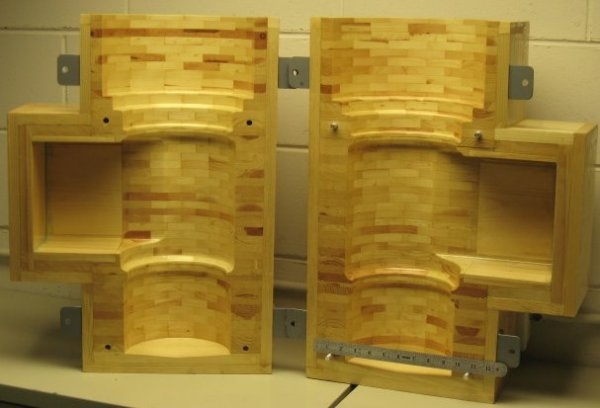
Fig. 25 Finished core box.
A total of about 500 pie-shaped pieces of pine (aged for 3 years) were cut for this pattern. They were then glued together to create semicircular polygons, as shown in previous pattern work. After gluing, they were joined and planed flat, parallel, and of constant thickness. The glues, used interchangeably, were Elmer's Professional and Titebond Two. There was no significant difference between the two brands.
Separate stacks with changing diameters (by design) were first glued together and turned on a lathe. To achieve overall coaxial registry, a 1/4-inch pilot on one piece engages a mating cavity on the adjacent piece.
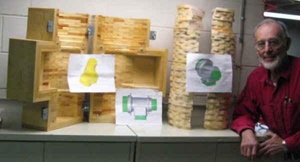
Fig. 1 Stacks of glued polygons next to pattern maker, Bill Volna.
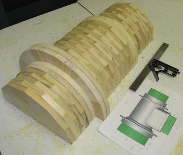
Fig. 2 Stack of layers ready for review, with CAD drawing.
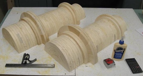
Fig. 3 Both halves with trimming completed.
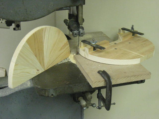
Fig. 4 Note: The radial, rather than the tangential, wood grain on this layer of the pattern enhances resistance to breakage during handling in the foundry.
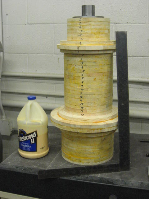
Fig. 5 Layers glued together in four sub groups to minimize excessive overhang during lathe work.
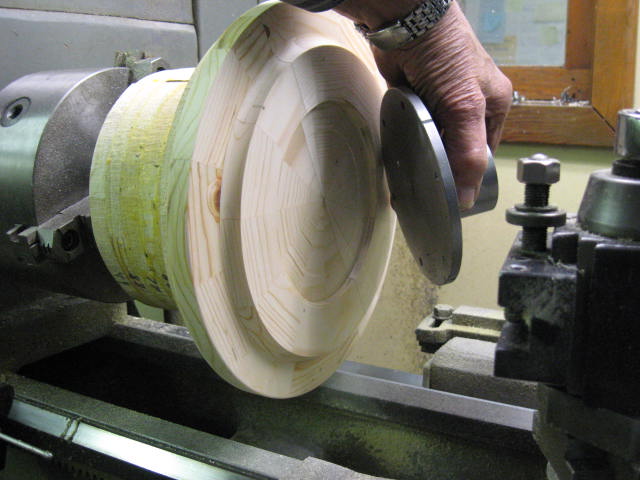
Fig. 6 First subgroup in lathe with custom face plate to be attached for added support.
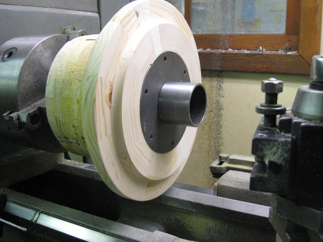
Fig. 7 Face plate nested in a concentric cavity ready for lag bolts.
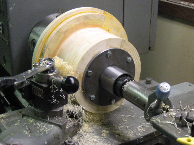
Fig. 8 Tail stock live center bearing on face plate center for added support.
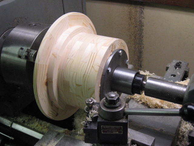
Fig. 9 Lathe work finished on this sub group.
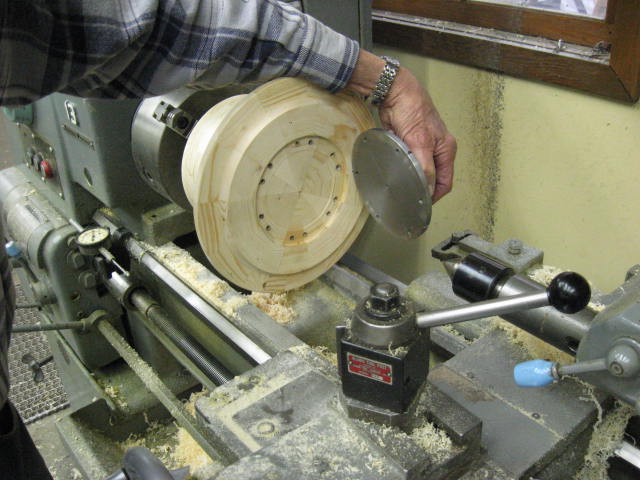
Fig. 10 Face plate removed.
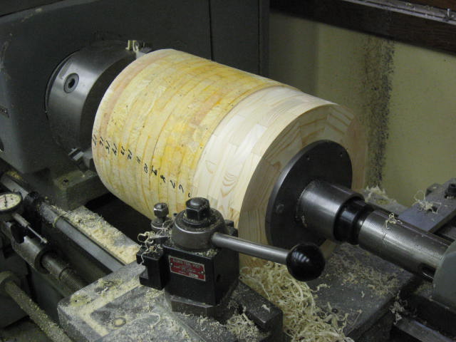
Fig. 11 Turning the large center section sub group.
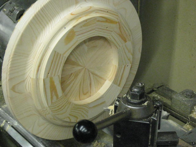
Fig. 12 Fig. 12 Note the radial wood
grain on the rim and tangential
grain on the body (see Fig.4)
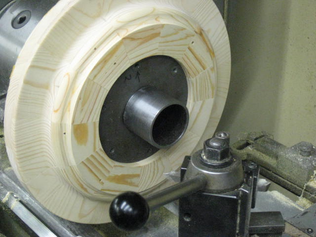
Fig. 13 The use of custom-made face plates
proved very successful.
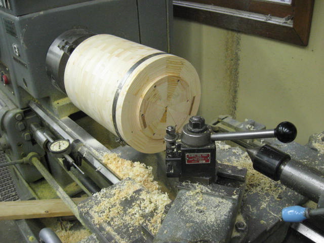
Fig. 14 A steel hose clamp was used for lathe work on this longest sub group, instead of gluing two halves together with a layer of Kraft paper in the joint as described in the "tee" casting build.
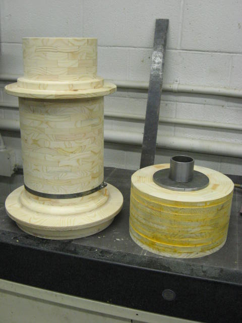
Fig. 15 The last sub group ready for turning.
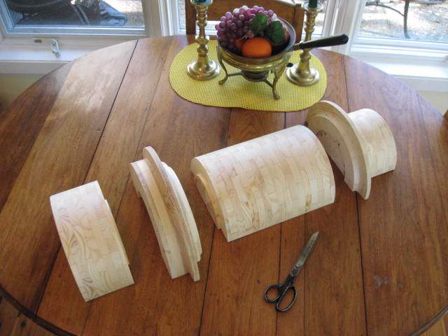
Fig. 16 Lathe work done on four sub groups.
Note the cavities and mating pilot diameters for concentricity during final assembly.
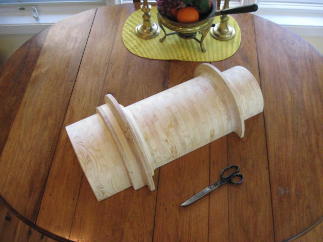
Fig. 17 Sub groups pushed together.
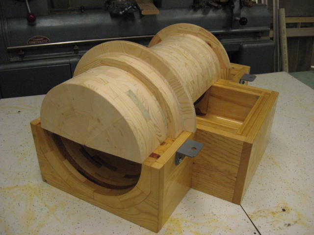
Fig. 18 The pattern, which gives shape to the outside of the casting, is spotted above the core box, which is used to make the casting hollow.
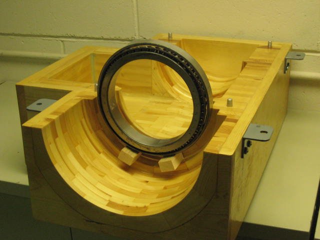
Fig. 19 One of two Timken 36600 bearings used on each end of the finished casting to support the 5.75 in. spindle of the altitude axis.
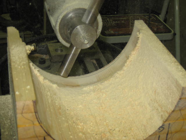
Fig. 20
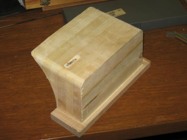
Fig. 21
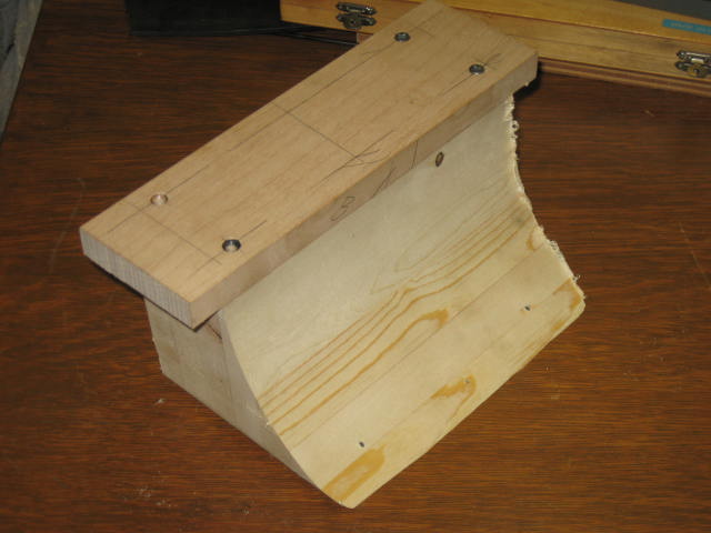
Fig. 22
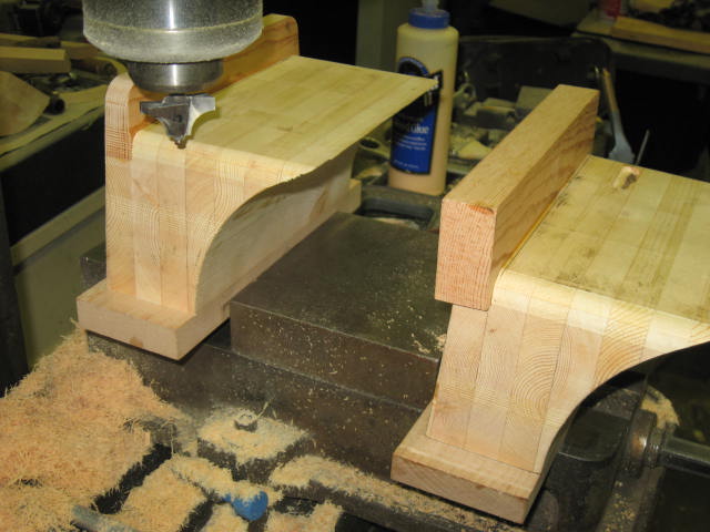
Fig. 23
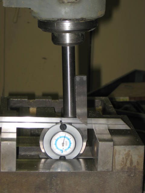
Fig. 24
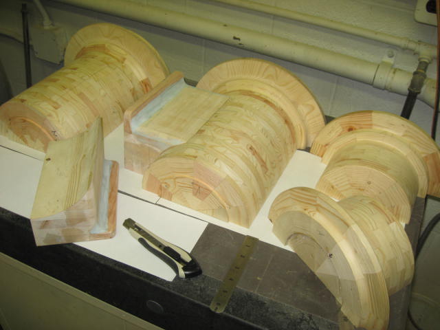
Fig. 25
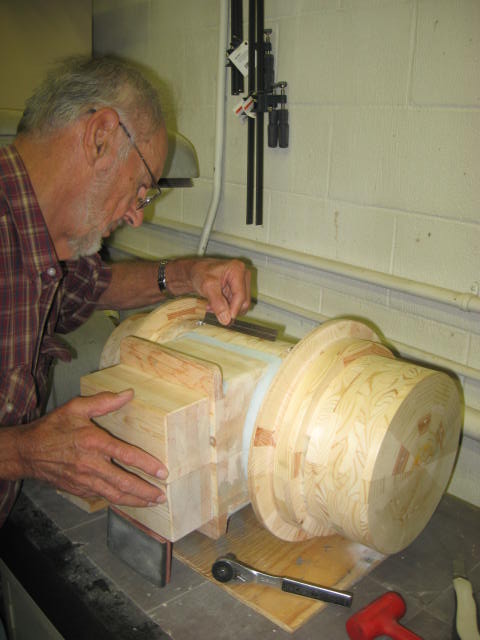
Fig. 26
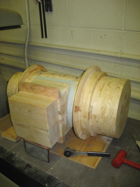
Fig. 27